Password protected page
You will need to enter the username and password created when the module was first initialised.
Firmware prior to the PSTI legislation of April 2024 used a factory default which is left here for reference:
Username: admin
Password: K2AUDIO!
Configuration options
Ping
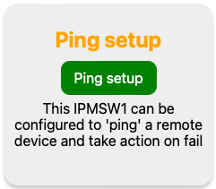
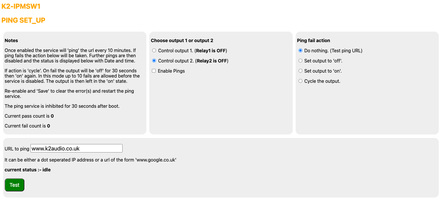
The built in Ping feature can be set to monitor an IP address (or url) and perform an action if there is no reply to the ping request. This can be very useful for monitoring and automatically power cycling failed network equipment.
A ping consists of a set of four requests with a two second timeout per request. Once enabled this set of four requests is sent every 10 minutes. As soon as one successful reply is received no further requests will be sent from that set. Only one of the four requests needs a reply for the process to be deemed successful. Failure of all four requests will trigger the selected response; either power cycle or turn the selecte output on or off.
Time
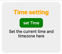
If the check box for internet time is active the IPMSW1 will attempt to communicate with an Internet time server. The status will tell you if this has been successful. Note that this may take a few seconds to refresh after the "update" button has been clicked. If you don't wish to use internet time disable the check box, click update and then manually enter the desired settings.

Switch settings
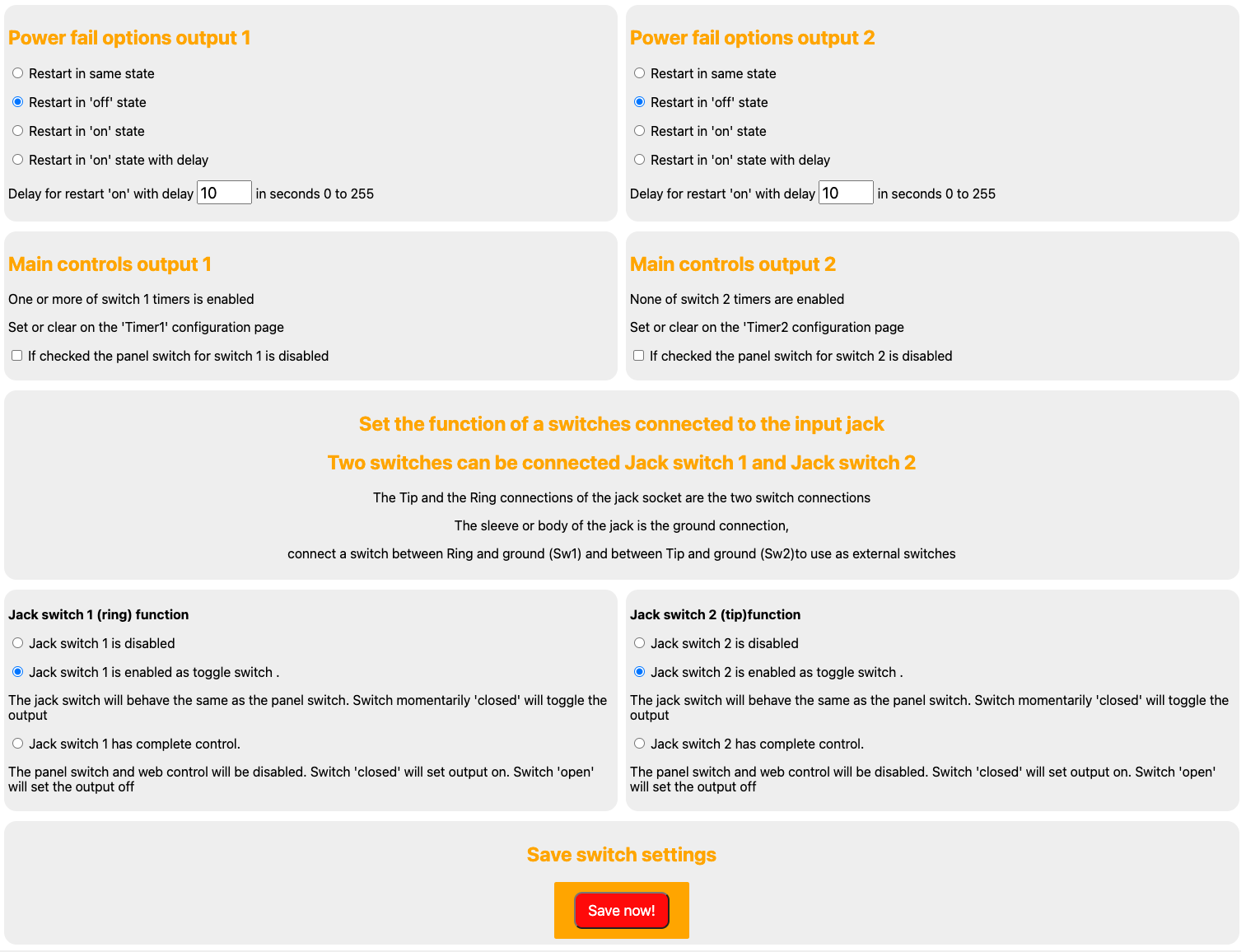
Here you can set your preference as to what should happen in the event of a power failure. The delayed start option is useful to bring a NAS back on line before other systems.
You can enable or disable the front panel manual buttons for each switch individually.
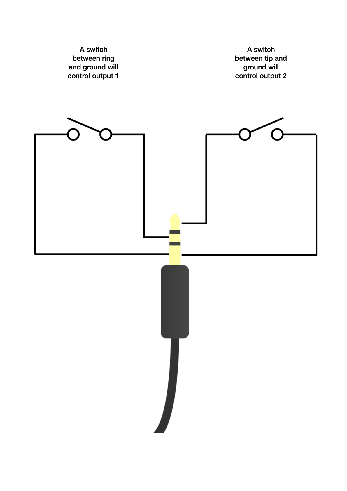
The front panel 3.5mm jack can also be wired to an auxiliary switch to act as a wired remote control.
Module IP
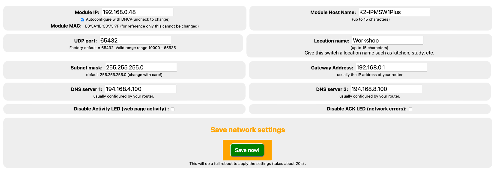
This is where you can change it from the DHCP assigned to one that better suits your network if required.
Module MAC
For info only, it is not possible to alter this.
Module Host Name
Change as required if you have multiple modules on the same network.
UDP port
The default is port 65432 and it is recommend to leave at this. Should you wish to change enter the new port number and click to save - the valid range is from 10000 to 65535. Please see the API menu option above for more information on UDP control.
Location name
Useful if you have more than one switch on the network.
Subnet Mask
The default is 255.255.255.0 and we recommend you leave it set at this. The only time this should really altered is if you have more than 255 devices on you local network.
Gateway address
If the initial DHCP was successful this is usually set to the IP address of your router, and can be manually entered if required.
DNS Server 1 & DSN Server 2.
The Domain Name Servers will usually have auto configured with the initial DHCP and can be edited if required.
Disable Activity LED
The green activity LED will normally flash briefly whenever the web pages are being accessed. The LED will also flash continually along with the red ACK LED when the switch is in access point (AP) mode. Check and save to disable if required.
Disable ACK LED
The red ACK (acknowledge) LED will normally flash briefly to confirm data sent and received. The LED will also flash continually along with the green Activity LED when the switch is in access point (AP) mode. When there is no valid network connection the red LED will flash continually. Check and save to disable if required.
