Connections & Indicators
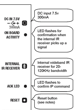
On Board Activity LED
Will flash whenever the internal receiver detects a signal. It is recommended that the on-board receiver is disabled for normal use unless specifically required as it may pick up emitted signals within a cabinet.
Acknowledge LED
Will normally flash once every five seconds unless learning IR code (see operation section)
Reset Button
If you get a problem with the IR Commander, pressing the reset switch until the acknowledge light comes on will reboot the module with the current settings. Can also be used for a full factory reset as detailed on the reset link opposite.
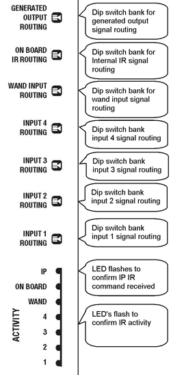
Generated Output Routing
Use the dip switch bank to determine which of the four outputs you would like generated (TCP/IP network) IR commands to be directed to.
Wand Output Routing
Use the dip switch bank to determine which of the four outputs you would like signals from direct wand input to be directed to.
Input 1, 2, 3 & 4 Output Routing
Use the dip switch bank to determine which of the four IR outputs you would like signals received by each of the numbered wand inputs to be directed to.
Net IP Activity LED
will flash when TCP/IP IR commands are received.
Activity LED's
Will flash to confirm onboard IR activity.
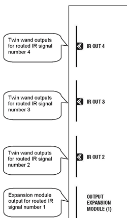
IR Outputs 1, 2, 3 & 4
Connections for IR emitter wands. There are two (common) jack sockets for each numbered output and number 4 (only) is for the optional CAT5 Output Expansion module. See "optional accessories" for a list of emitter wand options.
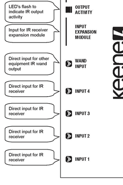
Output Activity LED's
Will flash whenever IR is emitted.
Input Expansion Module
Connection for the optional input expansion module. allows up to four remote IR receivers to be connected via CAT5 cable.
Wand Input
Allows the IR emitter socket of a remote extender (e.g. Powermid), normally connected to an emitter wand, to be connected directly to the Commander as an input.
IR Inputs 1, 2, 3 & 4
Connections for IR receivers. See "optional accessories" for a list of compatible receivers.